Herkulex Table Rover
I made a new robot this weekend. It’s not a biped, but it does use Herkulex servos, which are intended primarily for bipeds. I wanted to see how well they would work as closed-loop gearhead motors. (That, and I had a Magician chassis lying around just begging to be put to use.)
Mechanics
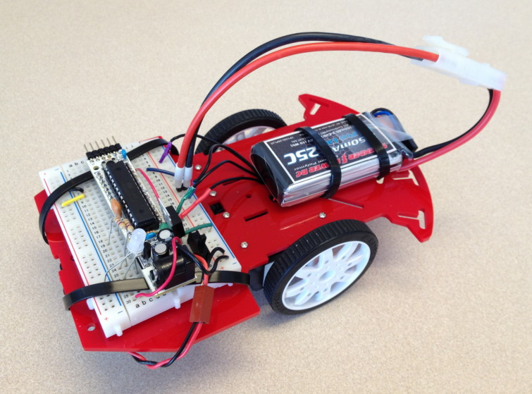
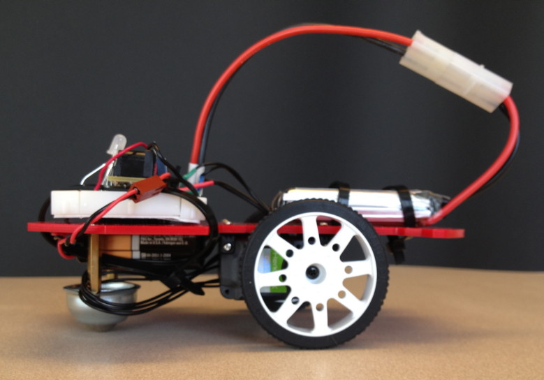
I began by stripping down the Magician to just the lower chassis and caster. I ordered a set of Herkulex wheels with tires ($4/pair at Road Narrows), which mount in place of the standard servo horn. The servos came with all other mounting hardware I needed, but of course none of the holes on the Magician happened to line up. A few minutes with the drill press solved that, and I soon had two the servos and wheels attached to the chassis. I ran a standard Herkulex cable from one servo to the other, and from that one, ran the hacked cable from my first experiments up through the deck to plug into the breadboard. Mechanics done.
Electronics
Since I already knew how to control the Herkulex servos from an Arduino, I decided to keep things simple and use Arduino again. But this time I went with the Really Bare Bones Board from Modern Device. This is a great little Arduino clone that fits on a breadboard, making it perfect for experimentation; yet it’s all through-hole components with a socketed chip, so it’s highly hackable. It’s also cheap enough that I bought several a few years back, and always have some lying around.
I plugged the RBBB into a 30-row breadboard, strapped it onto the chassis with cable ties, and plugged in the Herkulex wires based on my previous experiments. Electronics done.
Motor Power
I’ve been getting by for far too long using alkaline batteries, which I fully recognize is lame. So for this project, I finally decided to take the plunge and use a proper Lithium-Polymer pack.
It turned out to be quite easy. I got a 2-cell pack from HobbyTown (1350 mAh capacity, 7.4V nominal). This is in fact exactly the voltage the Herkulex servos are optimized for, and clearly how the Dongbu engineers expect you to power them. I put a standard male Tamiya connector (also purchased at HobbyTown) on the battery pack, and plugged it into a Tenergy smart charger (after switching it to its 7.4V setting). In an hour or so, the light was green, and the battery was ready to go.
To connect it to the breadboard, I took another Tamiya connector that already had 10 cm of wire on it, and simply soldered the wires onto a 2-pin male header.
Note that I did have a bit of excitement during all this. A couple of times, while putting the connector on the battery, I was insufficiently careful and allowed the bare ends to touch. This created a short circuit, resulting in sparks and the sweet smell of ozone. Thankfully, it did not result in the battery bursting into flame and burning the house down. But I still don’t recommend it. Any time you have bare wires connected in any way to a LiPo battery, they should be considered dangerous, and handled with great care.
Electronics Power
At this stage, I made all the connections, programmed my robot (see below), and took it for a spin. It worked — sort of. When the motors got up to full speed, they would often cause the voltage to sag just enough to case my RBBB to reset. I tried adding some fairly beefy capacitors, but it didn’t help much.
So, I took the easy way out, and stuck on a separate 9V battery just for the electronics. OK, I know I said I was avoiding alkalines, but it’s not so bad in this case; a 9V battery will power a RBBB for a long time.
Very astute observers may notice the extra voltage regulator on the breadboard, and wonder why it’s necessary. No good reason; the voltage regulator on this RBBB itself happened to be fried, and I was too lazy this weekend to properly replace it. So I stuck a 5V voltage regulator on the breadboard, and routed its output directly to one of the 5V pins on the RBBB.
Programming
This is the fun part. I used the standard Arduino environment, with the Herkulex library from Dongbu. Right after the #include for that, I put in a couple of #defines to identify which pins the servos were connected to, and which servo IDs were attached to the left and right wheels.
#include <HerkuleX.h>
#define RX   10        // Connected with HerkuleX TX Pin
 #define TX   11        // Connected with HerkuleX RX Pin
#define kRightWheel 1
 #define kLeftWheel 2
In the setup() function, I put some code to initialize communications with the servos, clear any errors they may be desperately trying to tell me about, and stop them if they happen to be running. (This can happen if, say, the board resets or loses power while the servos are running; they’ll keep running until somebody tells them to stop.)
Serial.begin(9600);    // Open serial communications
 HerkuleX.begin(57600, RX, TX);  // software serial
 delay(10);
// Clear errors on all servos
 HerkuleX.clear(kLeftWheel);
 HerkuleX.clear(kRightWheel);
// Stop the servos, if they happen to be running
 fullStop();
Everything’s ready to go, at this point. Using a Herkulex servo in continuous-rotation mode requires nothing more than calling HerkuleX.turn, and telling it which servo and how fast. You also get to turn on the servo LED at the same time, so just for fun, I made a little function to set the servo color based on its direction and speed, which gets called from two little helper functions that control the left and right wheel.
uint8_t colorForSpeed(int16_t speed) {
 // Select an LED color based on the direction and speed
 uint8_t color;
 if (speed > -512 && speed < 512) color = HERKULEX_LED_RED;
 if (speed > 64) color |= HERKULEX_LED_GREEN;
 if (speed < -64) color |= HERKULEX_LED_BLUE;
 return color;
}
void leftForward(int16_t speed) {
 // Send the speed and color to the servo
 HerkuleX.turn(kLeftWheel, speed, 1, colorForSpeed(speed));
}
void rightForward(int16_t speed) {
 // Send the speed and color to the servo
 HerkuleX.turn(kRightWheel, -speed, 1, colorForSpeed(speed));
}
(In case it’s not obvious, to go backwards, you simply call leftForward or rightForward with a negative speed.)
That’s the meat of the code; everything else is just gravy. I wrote a main program that moves the robot forward, at three different speeds, then turns it 90 degrees, and repeats. You can download the full source here.
Results
The video below shows my little rover rolling along its square path.
I’m very happy with how it all turned out. Unlike some other servos I’ve worked with (sorry, Robobuilder), the Herkulex servos were trivial to mount, and very solid. They move exactly as commanded, and with considerable authority. The wheels are low-cost and high-quality, and a convenient size for this sort of table rover.
Of course, this wouldn’t be the right solution to every wheeled problem. The gearing provided by these servos and wheels is more about power than speed. They also wouldn’t be appropriate for a very low-cost robot; if you don’t need precision or power, and don’t mind adding a motor controller, you can certainly find cheaper motors and gearboxes.
But consider what you get in such a convenient little package: each motor has its own smart motor controller, that monitors the built-in wheel encoder and maintains the speed you tell it. You literally need nothing else than a source of power and a controller that can speak 5V serial. As the saying goes: why reinvent the wheel encoder? I think I may never use a toy motor again.

This should be a kit – add a single axis gyro and accelerometer and you should have fairly accurate localization.