Getting Started with the Herkulex DRS-0101
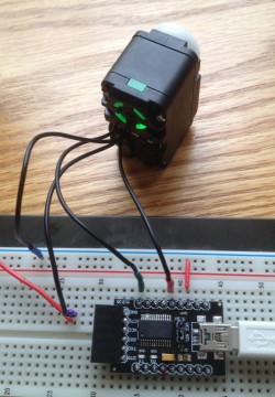
This week I finally found the time to hook up the Dongbu Robot Herkulex DRS-0101 servo that I picked up last month at the VStone Robot Shop in Tokyo. (If you’re here in the States, you can pick these up from Road Narrows.) After a few missteps, and some fantastic tech support from Dongbu Robot, I got it working. It really isn’t difficult; here’s how to do it, and a few tips I learned in the process.
(Non-disclaimer: I’m going to be gushing a bit about these servos, but I don’t work in any way for Dongbu Robot, VStone, Road Narrows, or anybody else… I’m just a happy customer.)
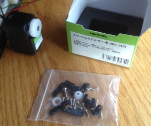
The image above shows the box (the white label was added by VStone). Open it up, and here’s what you’ll find:
The parts bag contains 16 screws, 8 brackets of various sorts, 2 cable guides, and an idler horn bushing and washer. Also in the box, but not pictured above, is a 200 mm connector cable.
RTFM (Read The Fine Manual)
Before going any further, you should find a copy of the manual. The best place to download this is via hovis.co.kr (here’s a direct link to the PDF), but you can also find it at places like Tribotix and via eBookBrowse. This is a surprisingly well-written manual (with just a couple of omissions that I’ll cover later). It describes everything from the parts inventory, to the dozens of ways the brackets can be used to connect two servos together, to the communications protocol.
Hacking the Cable
Unfortunately, the 2 mm keyed connector used by these servos is not available here in the States. I searched for a compatible connector; the guys at Dongbu searched; and I even ordered the Molex connector that looked like the closest match — but no luck. However, Dongbu does make a cable pack containing various lengths all ready to go, and Road Narrows expects to be carrying this soon.
So for now, to connect your Herkulex servo to anything else, you’ll need to just hack the cable that comes with it. I simply cut mine in half, so that I can make two custom adapter cables. The first thing I wanted to connect to was a breadboard, so I simply soldered a short piece of solid-core wire to each of the four wires in the cable, and covered the ugly with heatshrink tubing. I strongly recommend plugging the connector into the servo, and matching the pin colors shown on page 17 of the manual when you do this. If you don’t have blue, purple, red, and green heatshrink, then use white and color it with a sharpie. Having the right colors on your wires will help avoid mistakes in hooking it all up.
Hooking Up
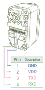
From left to right, as shown on page 17, the four pins are Serial Data Receive, Serial Data Transmit, Servo Voltage, and Ground. Now we come to the first omission in the manual: it says that the serial pins (RXD and TXD) use “TTL Level” serial, but they don’t specify whether this means 3.3V or 5V. I wrote to the Dongbu, and got clarification that these should be using 5V. (It’s possible that 3.3V would be enough, depending on where the 0/1 threshold voltage is set… but to be as reliable as possible, I plan to stick to the recommended 5V.)
So, to communicate properly, you need to find a host with 5V serial communications. There are plenty of 5V Arduinos out there that could probably do the job; or if using a 3.3V microcontroller, you could use a level converter. I wanted to start by controlling this thing from my computer, so I pulled out a DFRobot 3.3/5V FTDI Breakout board. This is a handy board that converts USB directly to logic-level serial, and lets you switch between 3.3V and 5V with a simple jumper (unlike the SparkFun equivalent, which requires resoldering). Use one of these, or your own favorite means of speaking 5V serial. Note that, as one would expect, the TXD (transmit) pin of your host should connect to the RXD (receive) pin of the servo, and vice versa. (Unless you’re using an improperly labeled serial adapter — see “Lessons Learned” below.)
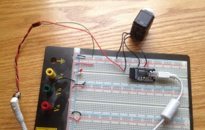
My prototyping setup. Ridiculously oversized breadboard is used to connect to 7.5V power (white jack at left); a USB cable to my computer (at right) connects to a FTDI breakout board (center), and these connect to the servo (top). Colors on servo wires correspond to pin colors on page 17 of the manual. (Click for larger image.)
Next, you need to provide power to the servo. Note that even though the communications pins use 5V, the servo itself needs more than this; it’s rated for 7-12V, but “optimized” for 7.4V. I used a 7.5V wall wart I had lying around. Be sure to connect the ground wire for this supply to the ground for your serial board (or microcontroller or whatever else you have); all voltages need a common reference (ground) level.
When you connect the 7.4V power, you should see the LED on the servo flash white once, and then go dark. This means that things look good from the servo’s point of view. If instead you see a red blinking light, then something’s wrong. Check all your connections; it almost certainly means you screwed up somewhere.
Speaking Herkulex
Now that everything’s hooked up, you’re ready to start talking to the servo! Set your communications to 115200 bps, 8 data bits, no flow control, and 1 stop bit (the standard “8N1” serial settings), and browse sections 4-6 of the manual. The communications protocol is a simple one, where you send a short binary command packet, and get back a binary reply packet. If you’re writing your own software for this communication, be sure to send bytes (e.g. 0xFF, or 255 in decimal) rather than characters (e.g. the two letters “FF”). I did my experiments using a terminal program called “Terminus” which is not released to the public yet (but should be soon — contact me if you want to get in on the beta test). This lets me easily send binary data, and read the binary data coming back from the servo.
Like all smart servos, every Herkulex servo has a unique servo ID that is stored in non-volatile memory. This is how they can all share the same servo bus, but you can address them individually. This brings us to the second (and last) omission in the manual: what is the default ID of a servo? It turns out that it’s 253 (0xFD) for a servo sold individually (servos that come with the robot kits have preassigned IDs starting at zero). This default ID matches all the examples shown in section 6 of the manual (pages 42-50), which is really great since you can try them out right away, without having to compute the checksum or otherwise think too much.
What if, for some reason, you have a servo whose ID is unknown? No problem; there is one command (STAT) that any servo will respond to, if you set the servo ID in your command packet to the magic value 254 (0xFE). You should of course only use this form of the command when you have only one servo connected to the communications bus. The response to this command will include the servo’s ID. I thought this was a nice safe place to start, even though I already knew my servo’s ID. So I started by sending:
FF FF 07 FE 07 FE 00
This includes the packet header (FF FF), length (07), the special broadcast servo ID (FE), the command (07, which is STAT), and two checksums (FE 00). The servo immediately replied:
FF FF 09 FD 47 B2 4C 00 00
The response packet is constructed in exactly the same way as the command packets: a header (FF FF), length (09), ID of the servo that’s replying (FD), a reply code (47, or STAT ACK), two checksums (B2 4C), and in this case, two data bytes (Status Error and Status Detail). So the servo here is saying, “I’m servo 0xFD, and all is well.”
At this point, I’d had enough chit-chat, and wanted to make something actually happen! The next safest thing to try, in my mind, is setting the LED. Example 1 on page 44 shows this request:
FF FF 0A FD 03 C0 3E 35 01 01
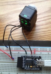
So I sent exactly that, and lo and behold — the servo turned its LED on green!
If you get this far, then the sky’s the limit! You’ll be able to set the ID of each servo to a unique value, and control any number of them on a bus. Make them turn continuously at any desired rate (which they will maintain regardless of load), or go to any position, over whatever amount of time you specify. Interrogate their current torque or temperature. Light up those LEDs like a Christmas tree if you like — the Herkulex servos are like minions in a box, ready to obey your every command.
Lessons Learned
I did make a few mistakes in the course of reaching this point. First, I had thought (and some casual testing with a multimeter suggested) that instead of cutting the cable, I could just cram some wires into one end of the connector. But, it turns out, this doesn’t make a very reliable connection — cutting a cable, and soldering on your own connector or breadboard wire, is a much safer approach.
Second, I was both lazy and in a hurry the first time, and didn’t shrink-wrap the wires. (Bad hacker, no biscuit!) This meant that I couldn’t easily tell them apart, and to make it worse, I read the diagram on page 17 backwards. In the table identifying the pins (shown at right), they’re labeled from right to left, not from left to right. So, in my first attempt, I hooked the cable up exactly backwards.
This meant that I was supplying 7.5V (and, in a moment of desperation, I tried 9V as well) to the serial comm pins (TXD and RXD)! To Dongbu’s great credit, the servo suffered this abuse without damage; it merely went into “alarm mode” with the blinking red light (which I now read as “hey dummy, you’re doing something stupid, please stop it”).
I also ran into a problem which had nothing to do with the Herkulex, and everything to do with this DFRobot serial adapter. In my first attempt, I was using the 6-pin female connector that comes presoldered to the end of the board. But as I later discovered, the pins on this header are mislabeled, with TXD and RXD identified as RXI and TXD. I decided to give up on that header, and just solder some male header pins down the sides of the board, which works better with a breadboard anyway. In this mode, everything seems to work properly. So, if you’re using this USB serial adapter, watch out for this issue — and if the servo won’t talk to you, check whether TX and RX might be reversed.
Finally, when I first ran into trouble (wondering about the voltage on the TXD and RXD pins), I submitted a support request through Dongbu’s contact form. Within a day, I received email back from Daniel Hwang, the sales manager for Dongbu’s robot line. He had consulted with his engineering staff, and gotten me exactly the answers I needed, clearly expressed in good English. Over the course of the next couple of days, I exchanged several more emails with Daniel, who was extremely patient and helpful, even though all the remaining problems I had were ultimately my own fault. In short, Dongbu’s customer support is just as outstanding as their engineering. I’m impressed.
Conclusion
Getting the Herkulex servos up and running is, in the end, pretty darn easy. The communications protocol they speak is simple and well-documented, and should be easy to interface with any microcontroller. Both the engineering and the customer support are high quality. Moreover, the shape of these servos, and the clever bracket system, should make them easy to integrate into custom projects. I frankly couldn’t be happier with them. Whether you need a smart gearhead motor, or a true smart servo, I recommend you give the Herkulex servos a try.
[UPDATED 10/22/12 to point to the official Herkulex manual PDF, thanks to a helpful correction from Daniel Hwang at Dongbu Robot.]

Hey nice job there. Any chance you could tell me what type of pic you used to communicate between servo. Im doing project on Herkulex DRS-201. Where im going to use 16f88 pic to communicate between 2 servos, to control XY table. I might change the pic later to communicate faster with servos. You can email on: lukasz.matuszak@hotmail.com
There was no PIC involved here; just a USB-Serial adapter from DFRobot (link is in the post above). Since then, I’ve also controlled these servos via a standard Arduino board (which is based on the ATmega328); I’ll write that up as soon as I get my hands on a couple more servos to make for a better demo. I don’t have much experienced with PICs, but any one with a 5V serial port ought to work fine.
Ok, that’s fine. By the way did you use HerkuleX Manager Software v1.2 . Or you just wrote c code on c program and that sends the signal throw USB cable to you DFRobot 3.3/5V FTDI Breakout. And that sends the signal to your servo. Cheers Lukas
I didn’t use HerkuleX Manager. I didn’t use a C program either. I used the “Terminus” terminal software mentioned in the blog post, and just sent bytes directly.
Any chance i could get that software from you ?
It’s not quite ready yet — almost, but not quite. Keep your eye on this blog; I’ll be sure to write about it when it’s ready.
Also, if you have an Arduino, watch for an upcoming post about controlling the Herkulex servos with one of those!
Hi, im trying to make a node js library for manage the motors, but i have some questions about the way i have to send the hex code. But i had not sucess trying to talk with dongbu support, can you give me the email you used to talk with them??
HI Joe
Nice work! I have a setup here where I try to talk to my DRS-0101 directly from the computer without arduino. I’m using Dongbu’s supplied serial adapter. Right now I made a small Processing sketch w the Serial library, where I connect to the right com port and I try to write some of the commands you described above to the servo. But I don’t get a response. Any ideas?
http://www.processing.org/reference/libraries/serial/Serial_write_.html
I know you posted this a long time ago. Just in case you or one of your readers is still in search of a socket for the Dongbu connector. I just got these from Digikey and they fit perfectly: http://www.digikey.com/product-search/en?KeyWords=A98590-ND&WT.z_header=search_go
It’s from TE Connectivity and Part# is 292161-4 (Digikey part# A98590-ND)
Fantastic! That’s really helpful. Thank you for sharing it!
Thanks a lot Markus ! I was searching them for several weeks now…
You made my day 🙂
Hi, thanks for the nice tutorial. I am trying to set up a servo controlled via PC, but with no success. Like yourself I opted to skip the battery and use a dc power supply (10V in my case). The thing is, after powering up, with no other connections made, the servo flashes white once and then goes blinking red. Do you know if this is expected? Is my servo healthy or is this something to be worried about?
I don’t think that’s anything to worry about — I think that’s what the servos do until they get a reset signal from the controller. This way, if the controller is dead or a connection is broken or some such, you find out about it right away!
How can I change the tick time of servo as when I am trying to change it via python it throwing an error but when done via herkulex manager it works . For changing tick time I m writing to 57 Ram register I knw its RO register but then how can I change it